SHELL & TUBE HEAT EXCHANGER DESIGN
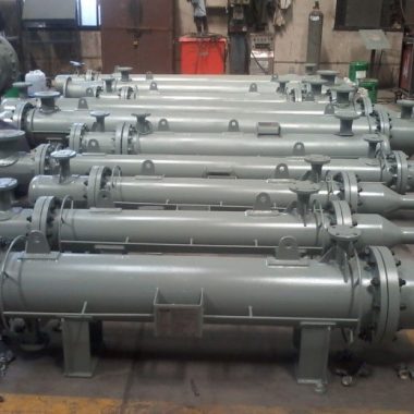
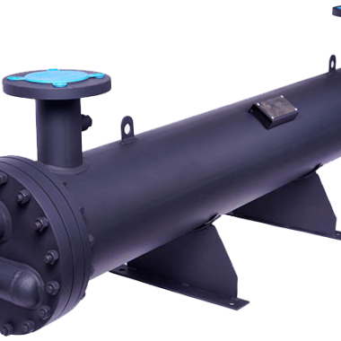
SHELL & TUBE HEAT EXCHANGER
This exchanger is filled with two fluids that have differing beginning temperatures. One flows inside the shell (the shell side) while the other flows outside the tubes (the tube side).
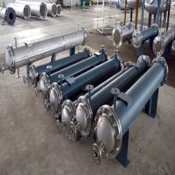
SHELL & TUBE HEAT EXCHANGER DESIGN
The shell and tube design is flexible and can take many different forms. Typically, holes in tube sheets are used to connect each tube’s ends to plenums (also known as water boxes). The tubes can be either straight or bent into a U form, which are known as U-tubes.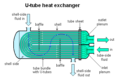
Large heat exchangers known as steam generators, or pressurized water reactors, are two-phase, this heat exchangers that commonly have U-tubes. They are utilized to generate electricity by turning recycled water from a surface condenser into steam. On the tube side, the majority of shell-and-tube heat exchangers have 1, 2, or 4 passes. The number of times fluid in the tubes passes through fluid in the shell is indicated by this. The fluid enters each tube at one end and exits it at the other in a single pass heat exchanger.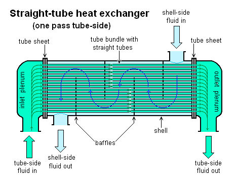
In power plants, one-pass straight-tube heat exchangers are frequently used as surface condensers. Because the fluid can enter and exit on the same side, two- and four-pass designs are frequently used. Because of this, construction is substantially easier.
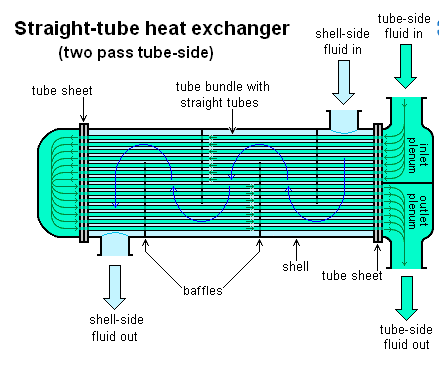
To prevent the fluid from taking a shortcut via the shell side and leaving useless low flow volumes, baffles are frequently used to direct flow through the shell side. To ensure that the tube bundle may still be removed for maintenance, these are typically fastened to the tube bundle rather than the shell. Counter-current heat exchangers are the most efficient because they allow for the highest log mean temperature difference between the hot and cold streams.