- 30 October, 2024
- Posted in Sanju
Flow Arrangement on Heat Exchanger
Introduction
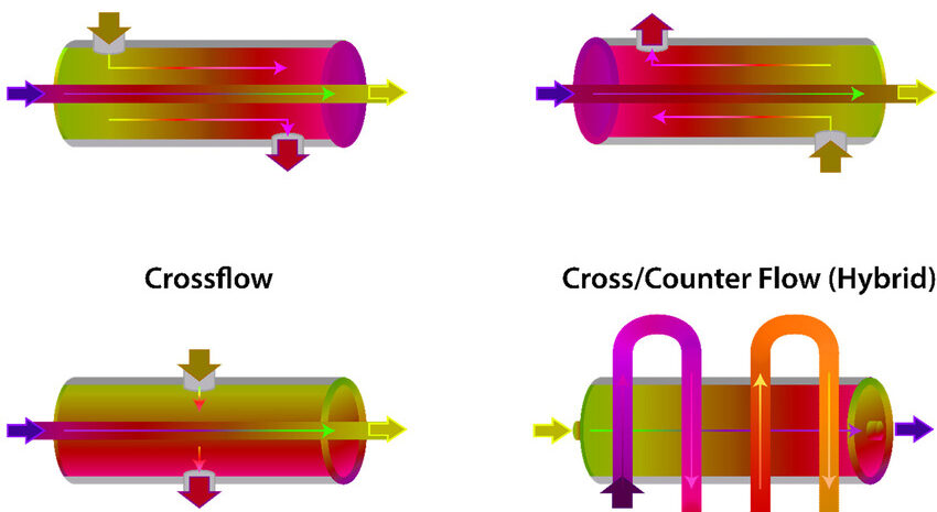
Flow Arrangement on Heat Exchanger of fluid flow within a heat exchanger plays a vital role in determining its thermal efficiency, effectiveness, and suitability for various applications. Known as flow arrangement, this configuration dictates how two fluids—typically a hot and a cold one—move in relation to each other inside the heat exchanger. The three primary flow arrangements—counterflow, parallel flow, and crossflow—offer distinct advantages and limitations depending on the desired heat transfer rate, temperature control, and operational requirements. By understanding these flow patterns, industries can select the optimal heat exchanger design to maximize energy efficiency, minimize operational costs, and ensure effective thermal management across a wide range of applications, from HVAC systems to industrial cooling processes.
- Heat Transfer Efficiency:
- Counterflow arrangements enable the highest possible temperature difference between fluids along the exchanger, which maximizes heat transfer efficiency. This is ideal for processes requiring high thermal energy exchange.
- Parallel flow has a declining temperature gradient from the beginning to the end, leading to less effective heat transfer, which limits it to low-efficiency applications.
- Crossflow achieves intermediate efficiency and is often suitable when one of the fluids has a large temperature difference and the other does not.
- Outlet Temperature Control:
- In counterflow, outlet temperatures can approach the inlet temperature of the opposing fluid, providing better control over the final fluid temperatures. This is useful for applications needing close temperature matching.
- Parallel flow restricts the outlet temperature differential, which may not meet precise temperature requirements.
- Crossflow is generally less controllable than counterflow but more adaptable than parallel flow, making it versatile for variable conditions.
- Pressure Drop and Energy Consumption:
- Counterflow configurations often incur a higher pressure drop due to longer, opposing paths, increasing energy costs for pumping but enhancing overall heat transfer.
- Parallel flow typically has a lower pressure drop, making it more energy-efficient in terms of fluid movement but with compromised heat transfer.
- Crossflow systems generally experience moderate pressure drops, balancing efficiency and energy costs.
- Fouling Resistance and Maintenance:
- Counterflow exchangers tend to have higher fouling resistance since the opposing flow pattern creates turbulence, which helps in reducing fouling rates.
- Parallel flow systems may have a higher risk of fouling, as lower turbulence can lead to buildup over time, especially with viscous fluids.
- Crossflow units allow for easy access to components, making cleaning easier, which is an advantage in fouling-prone environments.
- Compactness and Space Efficiency:
- Counterflow designs are more compact and offer high efficiency in a smaller footprint, ideal for applications with space limitations.
- Parallel flow exchangers are often bulkier due to the need for larger areas to compensate for lower heat transfer efficiency.
- Crossflow exchangers are commonly compact and well-suited for air-cooled exchangers and applications needing smaller units.
- Cost and Manufacturing Complexity:
- Counterflow exchangers tend to be more expensive due to the need for advanced design and materials to handle high-temperature gradients and pressure differences.
- Parallel flow exchangers are generally simpler and cost-effective, making them popular for low-cost or small-scale operations.
- Crossflow exchangers strike a balance in complexity and cost, particularly in air-based systems where the exchanger must be compact yet effective.
- Application Suitability:
- Counterflow is often chosen for energy recovery applications, high-temperature processes, and systems where heat efficiency is a priority.
- Parallel flow works well in low-temperature applications where high heat exchange isn’t essential, such as basic fluid heating.
- Crossflow is favored in air-cooled exchangers, HVAC, and situations where moderate efficiency is sufficient but space constraints are critical.
- Scalability and Design Flexibility:
- Counterflow systems can be scaled for very large or very small applications due to their high efficiency.
- Parallel flow designs are less scalable when high efficiency is required, making them suitable for applications with modest heating or cooling needs.
- Crossflow designs offer flexibility in layout, allowing customization based on spatial requirements, making them adaptable across various industries.
- Thermal Stress Management:
- Counterflow designs can manage higher thermal stress due to a gradual change in temperature across the exchanger, enhancing durability.
- Parallel flow configurations are less effective in managing thermal stress, which can lead to material degradation in high-temperature applications.
- Crossflow exchangers provide moderate thermal stress management, typically suitable for intermediate temperature ranges.
Conclusion
The flow arrangement within a heat exchanger is crucial to optimizing performance, impacting everything from heat transfer efficiency to energy consumption and maintenance requirements. Each arrangement—counterflow, parallel flow, and crossflow—offers unique benefits suited to specific thermal needs and operational constraints. By choosing the correct flow configuration, industries can maximize heat exchanger effectiveness, improve temperature control, and reduce costs, ensuring that the heat exchanger aligns with the demands of the application. In sum, understanding and selecting the right flow arrangement is key to achieving sustainable, high-performance thermal management in diverse industrial and commercial environments.


