Shell & Tube Heat Exchangers India
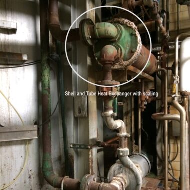
SHELL AND TUBE HEAT EXCHANGER
There are two fluids in this exchanger, and their starting temperatures vary. One flows on the shell side of the shell, and the other flows on the tubes’ exterior (the tube side).
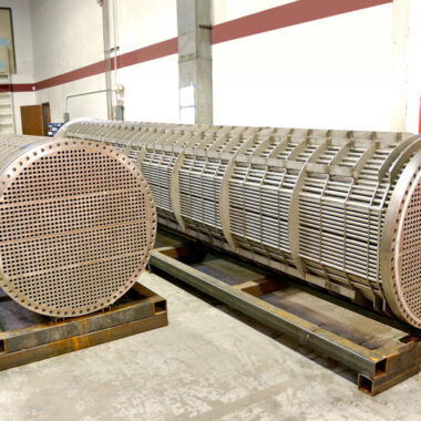
SHELL & TUBE HEAT EXCHANGER DESIGN STRUCTURE

U Tube Heat Exchanger
The shell and tube structure is adaptable and can take on various shapes. Typically, plenums are connected to the ends of each tube by perforations in tube sheets (also known as water boxes). The tubes can be twisted into a U shape, which are known as U-tubes, or left straight. Large two-phase heat exchangers using U-tubes are frequently seen in pressurized water reactors, steam generators, and other large heat exchangers. Through the conversion of reclaimed water from a surface condenser into steam, they are used to produce power. Most shell-and-tube heat exchangers feature 1, 2, or 4 passes on the tube side. This indicates the number of times fluid in the tubes flows through fluid in the shell. In a single pass heat exchanger, the fluid enters each tube at one end and exits it at the other.

One-pass straight-tube heat exchangers are widely employed as surface condensers in power plants. Two- and four-pass designs are widely employed since the fluid can enter and exit on the same side. As a result, building is considerably simpler.
Baffles are typically employed to direct flow through the shell side in order to prevent the fluid from bypassing it and leaving worthless low flow volumes on that side. These are often fastened to the tube bundle rather than the shell to guarantee that the tube bundle can still be removed for maintenance. Because they enable the largest log mean temperature differential between the hot and cold streams, counter-current heat exchangers are the most effective.